The masonry wall panel element allows you to easily model, analyze and design masonry walls for in plane loads for these specific codes:
Here we will explain the calculation concepts and code references used in the program. For general wall panel information, see the Wall Panels topic. For information on masonry design rules, see the Masonry Wall - Design Rules (this is where you can define block thickness and self-weight). For masonry wall modeling procedures, see the Masonry Wall - Modeling topic. For masonry wall results interpretation, see the Masonry Wall Results topic.
Note:
This stress is calculated from Equation 8-24:
where:
In RISA Anv is defined as follows:
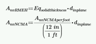
where:
Note:
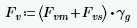
The program calculates the capacity, Fv, from Equation 8-22:
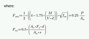

The program also checks to verify we do not exceed the Fv max value from Equations 8-23 and 8-24 (or interpolation between them) that is reported in the detail report.
Fvs is only required if fv > Fvm. If fv < Fvm, then the program will not add any shear reinforcement and Fvs = 0. If Fvs is required, then the program will back calculate a spacing, s, that will satisfy the steel shear capacity required. This shear spacing is reported in the detail report.
When shear reinforcement is required the program will also meet the d/2 or 48" spacing required by 8.3.5.2.1. If Fv max must be exceeded to pass the code check, the program will use Fv max as the capacity and state "Over Allowable" for the Shear Steel Spacing.
Note:
The axial stress in a wall due to axial forces, fa, is calculated as:
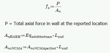
This is applicable for all out of plane
Note:
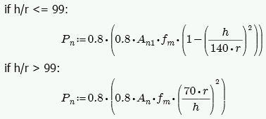
The calculation of Fa is per either Equation 8-13 or 8-14, depending on the h/r ratio. These equations match Equations 8-18 and 8-19 if you assume Ast = 0. RISA conservatively uses only the masonry in calculating the compression capacity. The equations are as follows:
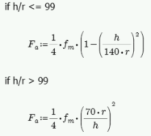
where:
Note:
These calculations are different depending on a cracked section or uncracked section. The wall is considered uncracked if fa (compression) > fb. The wall is considered cracked if fa (compression) < fb.
For uncracked masonry, the calculations are as follows:
where:
Because the masonry is uncracked, no stress can develop in the steel.
For cracked masonry, the program performs an iterative analysis to determine the section properties of the cracked wall.
The maximum masonry stress (fm) is obtained by solving the moment equilibrium equation as a quadratic equation of kd. This equation comes from vertical equilibrium ( C - P - T = 0 ).
Here is a representative wall with axial force and moment:
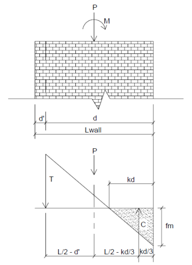
From this image we do a summation of moments about point T and come up with a quadratic equation in terms of kd.
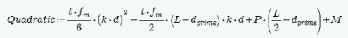
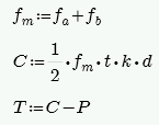
An assumption is made for fm = fa + fb, where fa = P/A and fb = M/S. From this C and T is determined. Once we calculate a value for T we can then define the boundary zone steel required. The final solution is determined through iteration. Each iteration of the steel area is based on the amount of steel needed to create a 0.005 ksi difference in the calculated bending stress (fb) and is carried out until the calculated value of required reinforcement is less than the reinforcement provided.
The final values are given in the detail report:
A good reference for this iterative procedure is Section 7.10.1 of Design of Reinforced Masonry Structures, copyright 2001 by Narendra Taly and published by McGraw-Hill.
From this analysis fm is calculated. This must then be broken down into fa and fb for the detail report. Because Section 8.3.4.2.2 states:
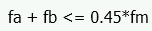
the proportion is simplified. RISA will simply take fa = P/An for fa and the remaining value from fm is used as fb.
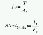
From the tension force in the wall, T, the program calculates the required number of boundary zone bars and places them in the wall. The reported code check is then based on:
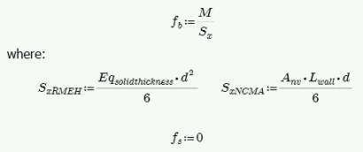
For unreinforced masonry, the Equation 8-15 is:

For reinforced masonry, Section 8.3.4.2.2 states:
Because of this provision, RISA defines:
Section 8.3.3.1 defines the allowable steel stress, Fs.
This is calculated from Equations 9-15 and 9-16:
Note:
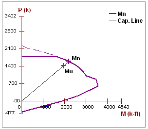
The Mn value is based on the axial - moment interaction diagram for the wall based on strain compatibility at different levels of axial force. Once the interaction diagram is created the Mu is plotted and the code check is then calculated.
Note:
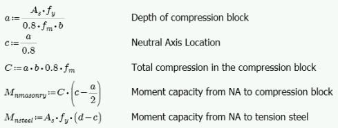
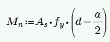
For a wall with no axial force, the Mn can be calculated from the equation:
Note:
The maximum usable masonry strain at the extreme compression fiber, emu, is assumed to be 0.0025. For assumptions of the extreme compression fiber for Seismic Detailing checks of Masonry Walls, refer to the Maximum Area of Flexural Tensile Reinforcement (Max. Flexural Rho Check - Strength) section.
The program calculates the capacity, Vn, from Equation 9-17:
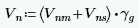
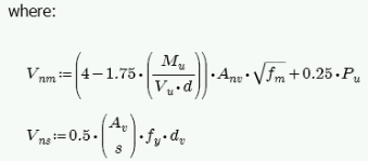

The program also checks to verify the Vn max value from Equations 9-18 and 9-19 (or interpolation between them) that is reported in the detail report is not exceeded.
Vns is only required if Vu > Phi*Vnm. If Vu < Phi*Vnm, then the program will not add any shear reinforcement and Vns = 0. If Vns is required, then the program will back calculate a spacing, s, that will both satisfy the steel shear capacity required and satisfy the maximum reinforcement spacing . This shear spacing is reported in the detail report.
If Vn max must be exceeded to pass the code check, the program will use Vn max as the capacity (so the wall fails in shear) and state "Over Allowable" for the Shear Steel Spacing.
Note:
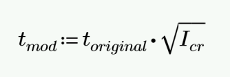
Out of plane deflections are calculated based on the Wall's Finite Element Analysis using a modified thickness, tmod, for the wall plates. The modified thickness is calculated using the wall panel's out of plate cracked moment of inertia, Icr, which can be input in the Advanced tab of the Wall Panels spreadsheet.
Note:
The original thickness of the wall panel is the actual thickness of the wall panel, not to be confused with the nominal thickness.
RISA-3D then uses Finite Element Analysis using the modified thickness of the plates to calculate the out of plane deflection of the wall.
For unreinforced masonry we use the same design provisions from reinforced masonry. Thus, we still use reinforcement for both the boundary zones and shear reinforcement (if needed). See the reinforced sections for more information on this design.
Note:
The in plane shear stress, fv, is calculated as follows:
The in-plane shear stress capacity, Fv, is calculated from Section 8.2.6.2. Because we do not know whether the wall is in running bond or not we omit options (c), (d), (e) and (f).
For unreinforced masonry we use the same design provisions from reinforced masonry. Thus, we still use reinforcement for both the boundary zones and shear reinforcement (if needed). See the reinforced sections for more information on this design.
Note:
Here we will talk about specific calculations regarding lintel design for allowable stress design.
Note:
This stress is calculated from Equation 8-21:

where:
The program calculates the capacity, Fv, from Equation 8-25, which is shown in the previous In Plane Shear Capacity Fv section.
The program also checks to verify we do not exceed the Fv max value from Equations 8-23 and 8-24 (or interpolation between them) that is reported in the detail report.
Fvs is only required if fv > Fvm. If fv < Fvm, then the program will not add any shear reinforcement and Fvs = 0. If Fvs is required, then the program will back calculate a spacing, s, that will satisfy the steel shear capacity required. This shear spacing is reported in the detail report.
When shear reinforcement is required the program will also meet the d/2 or 48" spacing required by 8.3.5.2.1. If Fv max must be exceeded to pass the code check, the program will use Fv max as the capacity and state "Over Allowable" for the Shear Steel Spacing.
Note:
The bond stress check is one that has been grandfathered in from the UBC-1997 specification section 2107.2.16 and is defined previously in the In Plane Bond Stress u section. Σo is the summation of the circumference of all vertical bars.
The bond stress capacity was defined previously in the Bond Stress Capacity U section.
The masonry bending stresses were defined previously in the Out of Plane Stresses fb and fs section.
Section 8.3.4.2.2 states:
Section 8.3.3.1 defines the allowable steel stress, Fs.
Here we will talk about specific calculations regarding lintel design for strength design.
Note:
The program calculates the capacity, Vn, total from Equation 9-17, which was shown previously in the In Plane Shear Strength Vn section.
The program also checks to verify the Vn max value from Equations 9-18 and 9-19 (or interpolation between them) that is reported in the detail report is not exceeded.
Vn,steel is only required if Vu > Phi*Vn,masonry. If Vu < Phi*Vn,masonry, then the program will not add any shear reinforcement and Vn,steel = 0. If Vn,steel is required, then the program will back calculate a spacing, s, that will satisfy the steel shear capacity required. This shear spacing is reported in the detail report.
If Vn max must be exceeded to pass the code check, the program will use Vn max as the capacity (so the wall fails in shear) and state "Over Allowable" for the Shear Steel Spacing.
Note:
Lintel design in RISA does not account for axial force, thus Mn is calculated simply from:
Here are the calculations of other values reported in the detail report: